ppModeler: Modeling a Sword Tutorial
ppModeler: Modeling a Sword Tutorial
Modeling the Blade
First, we will set up the view, with the reference in background.
The sword reference we will model is given by "Raziel" can be found here.
Open the view configuration window, either with the 'o' key, or with the icon
 :
:
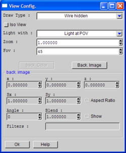
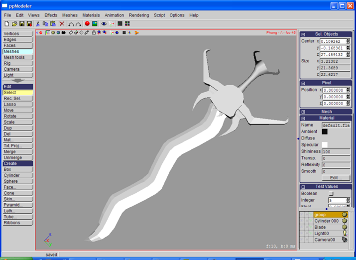
Click the 'Back Image' button and select the sword image. The picture appears in the view:
Now, you can scale/rotate/move the picture, and applied filter on it. In the filter combo box,
select a few time the 'Lighter' filter. Now, close the view Configuration window, we are
ready to model. But before, save your project with 'sword01.3de'. The '01' part is important,
because the 'File->Save Incremental' (F4 short key) will create new file with an increasing
number each time like 'sword02.3de', 'sword03.3de'...
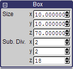
Create a Box ('Box' button in the 'Meshes' toolbox), and change the box parameters as shown
bellow:
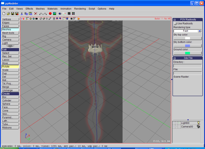
Press the 'x' key to move the point of view along the x-axis.
Move ( ) and scale (
 )
the box on the z-axis with the 3D manipulator (blue is for z constrained) in order to match
the position and length of the blade:
)
the box on the z-axis with the 3D manipulator (blue is for z constrained) in order to match
the position and length of the blade:
Now, switch to the 'Vertices' toolbox, and change the drawing mode to wireframe (with 'D'/'d' keys).
The drawing mode is indicated at the top right corner of the view.
Switch also to the parallel drawing mode with the '=' key.
Use the 'b' key to hide/show the reference image, and the ' ' key (space bar) to hide/show the
3D manipulator.
Activate the Rectangular selection tool ('Rec. Sel.' button or 'r' shortkey) and drag a
rectangle around a row of vertices to be selected:
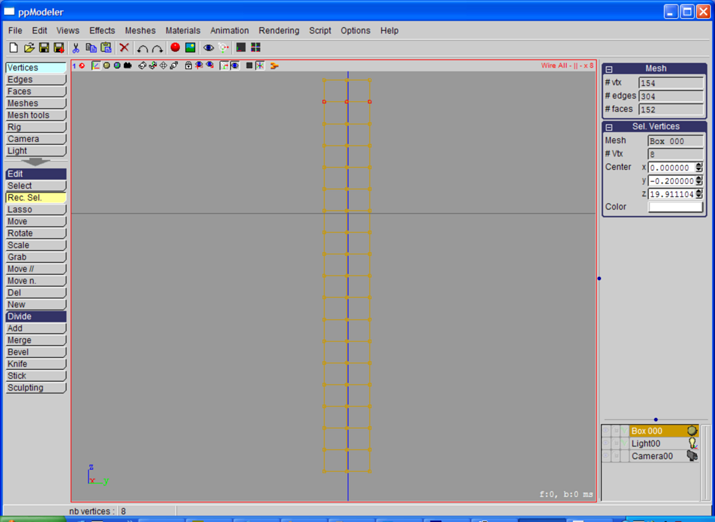
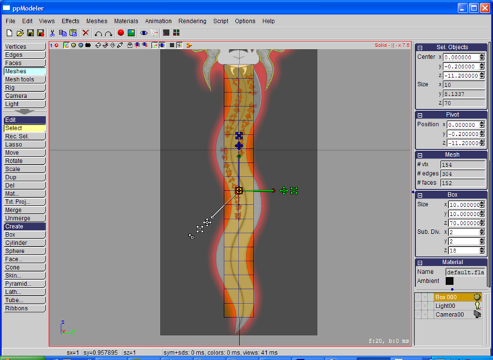
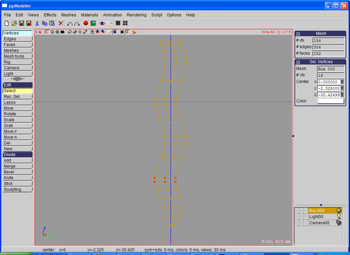
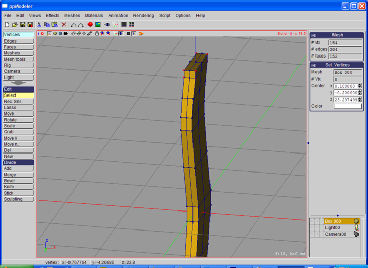
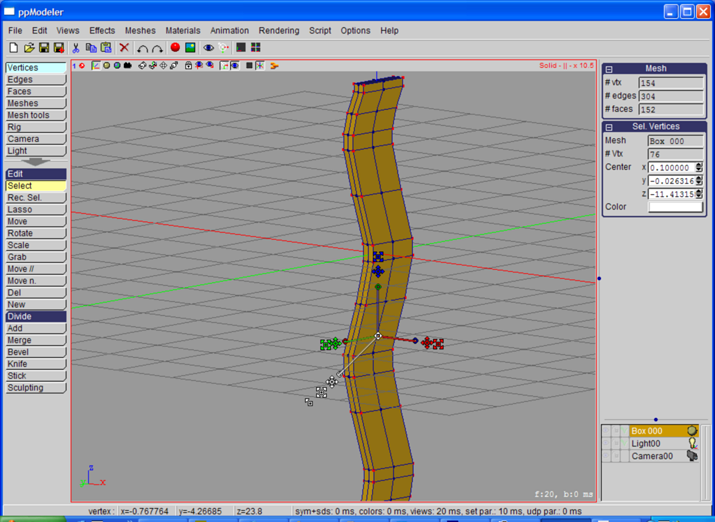
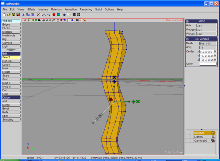
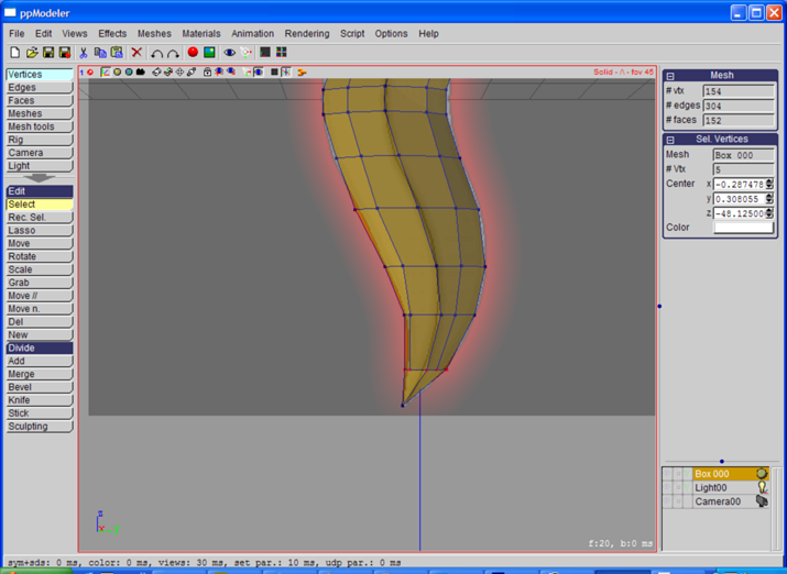
Select the horizontal row of vertices with the rectangle tool ('r' key) and move the selected vertices
with the 3D manipulator in the select tool ('s' key). Approximate the blade shape one row at a time
(only in the z-axis (blue) and y-axis (green):
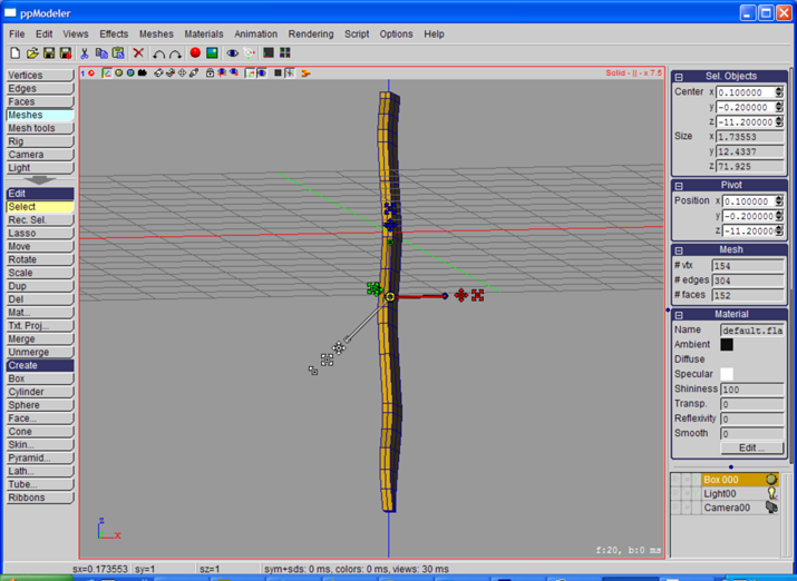
Go back to the 'Meshes' toolbox, and change the depth of the blade
(scale along x-axis (in red)):
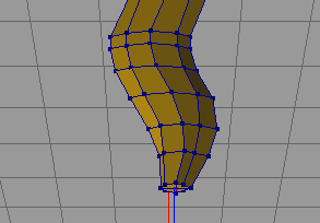
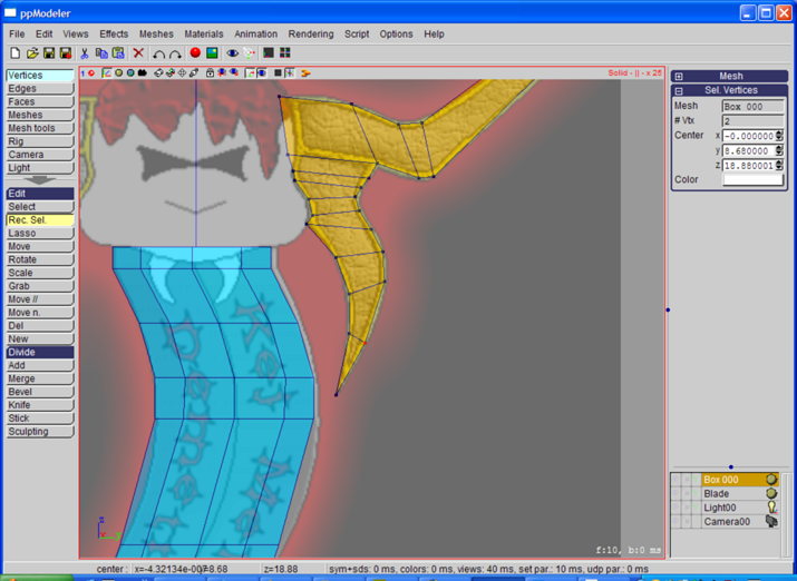
In the 'Vertices' toolbox, select the 8 corner vertices at the top of the blade:
Press 'L' to run the Loop selection tool. This operation selects the vertices along
the borders of the blade:
Scale in x the selected vertices:
Now, select the 4 vertices as shown below:

Use the Loop tool ('L' key), and move the selected vertices along the x-axis to make the
blade more sharp:

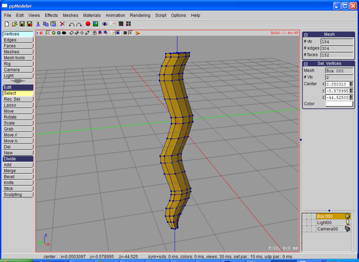
Do the same for the other side. Now, tweak the vertices to get a nice blade:
Select the bottom vertex:
And move it to the tip of the sword:
Last step, rename the mesh by clicking on the first part of the name in the
selection list (bottom left of the window):

Don't forget to save often, with the 'F4' key.
Modeling the Cross
Start by creating a new box, with 6 subdivision on y:
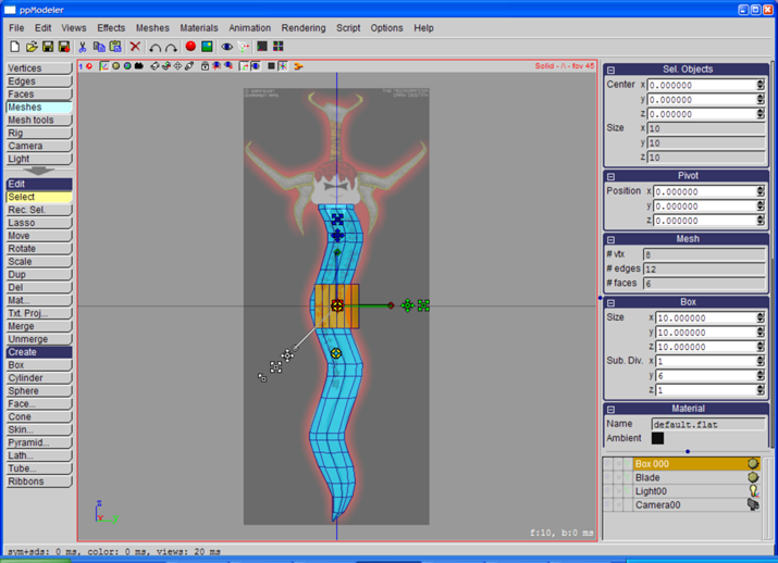
Move and Scale the with the 3D Manipulator:
Now, it is time to move the row of vertex. Swith to the 'Vertices' toolbox. Then, be sure to
be in wire all, parallel projection mode (with 'd'/'D' and '=' keys). The drawing mode
is indicated at the top right of each view. The projection mode follows with '||' for
parallel and '/\' for perspective.
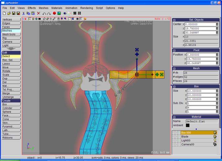
Using the 3D Manipulator and the select by rectangle tool, move each row of vertices in order
to approximate the desire shape:
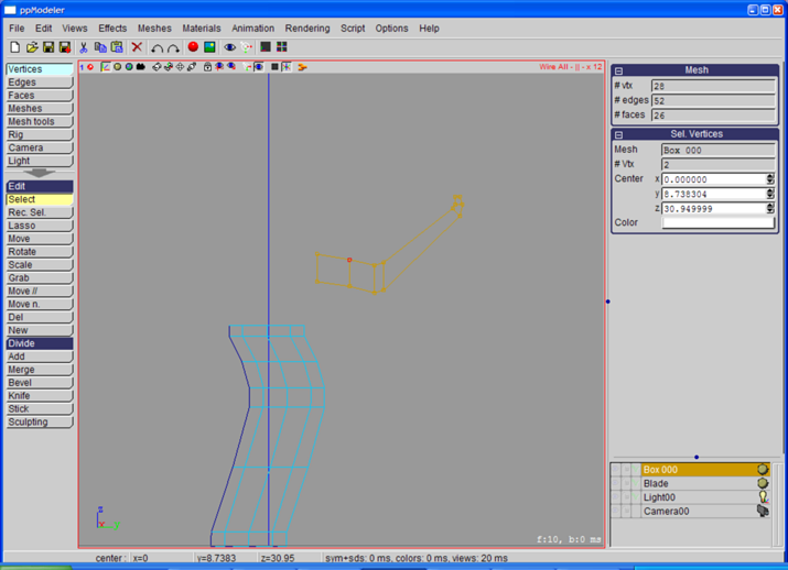
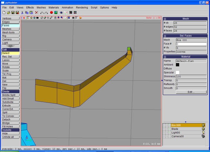
Now, switch to the 'Faces' toolbox. Select the top face:
Activate the 'Middle Split' tool:
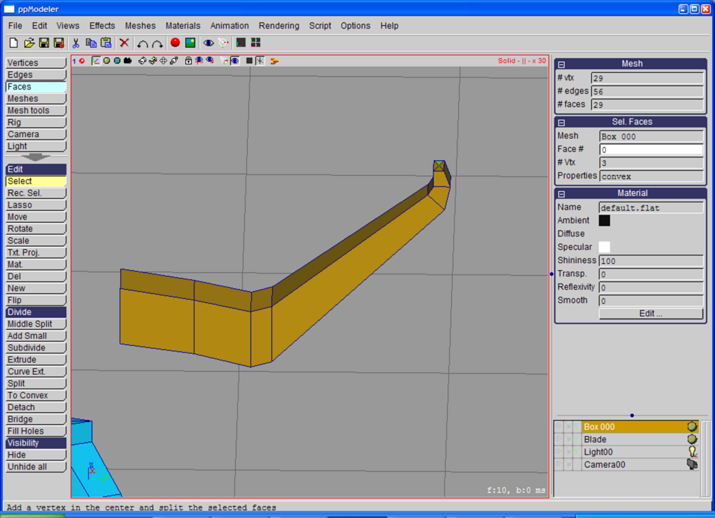
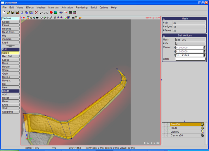
Back in the 'Vertices' toolbox, select the newly created vertex and move it to the top.
Now, it is also time to tweak a little the vertices:
Go to the 'Edges' toolbox, and select the two bottom edges shown bellow:
Activate the 'Cut & Join' tool, with 3 parts in the popup window:

And, this is the result:

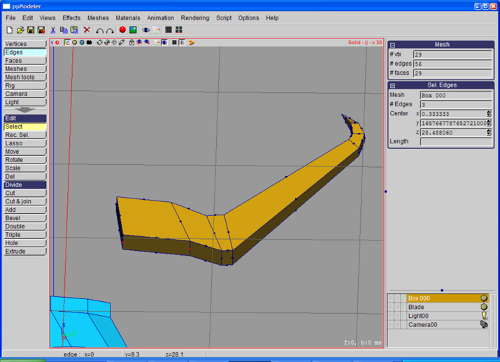
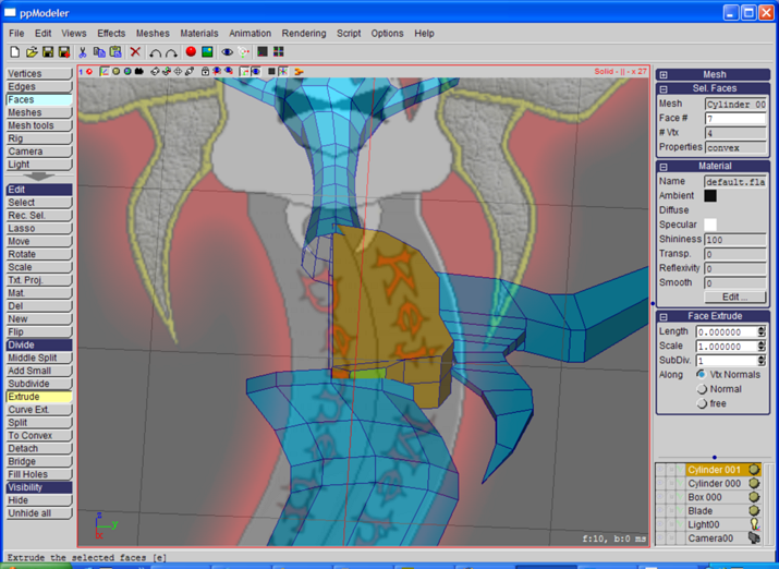
Now, back to the 'Faces' toolbox, select the newly created face:

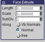
Activate the 'Extrude' tool. In the extrude parameters, choose extrude along normal:
Horizontal drag of the mouse extrudes the selected faces.
Shift drag changes the scale of the extruded part.
'Enter' starts another extrusion.
Extrude to get roughly the shape shown bellow:
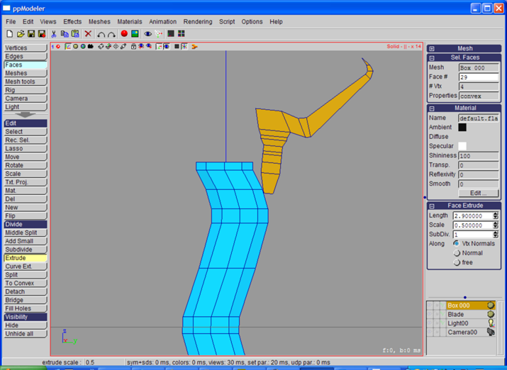
Leave the 'Extrude' tool by clicking on the 'Select' tool,
and activate the 'Middle Split' tool to add a vertex in the middle of the last face:
In the 'Vertices' toolbox, move the vertices to match the shape of the background image:
We will leave the cross here, and will finish it later
(no special reason, I just wanted to do so).
Modeling the Grip
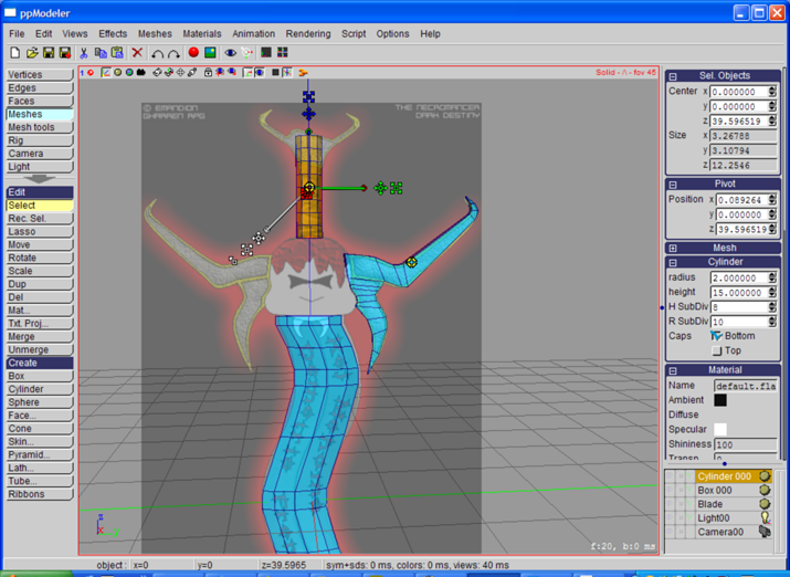
In the 'Meshes' toolbox, create a cylinder and change its parameter as shown bellow:
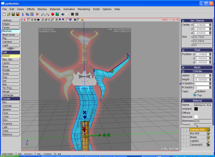
Move the cylinder in place:
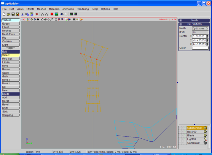
In the 'Vertices' toolbox, in wire mode, move the row of vertices:
In the 'Faces' toolbox, select the top left face:
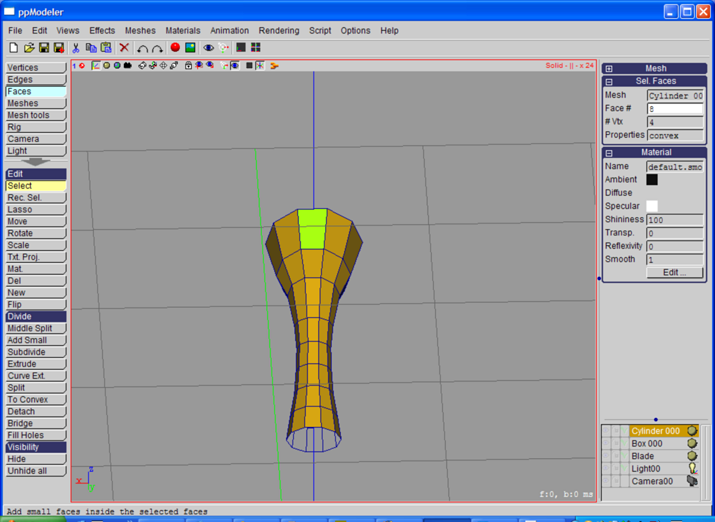
Use the 'Add Small' tool, and drag the mouse to change the size of the created face:
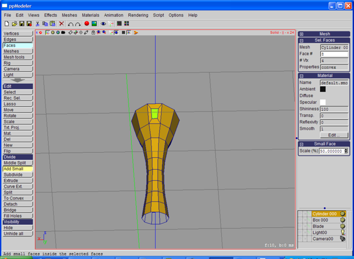
Do the same for the opposite face:
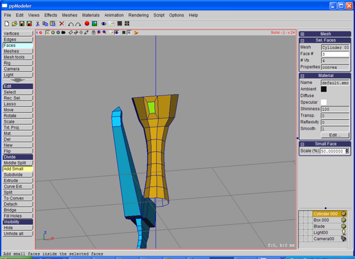
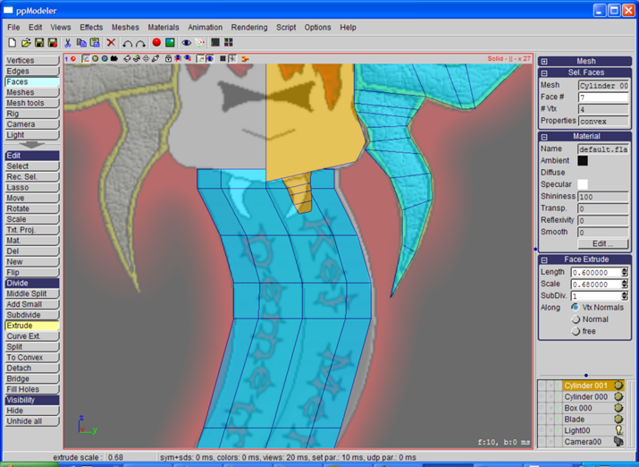
Now, we will use the 'Curve Ext.' tool. A normal extrusion can be performed, as before,
but I wanted to show another tool. A popup window is opened.
Enter the parameters shown bellow:
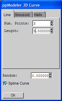
Leave the 3D curve toolbox by clicking on the 'Ok' button.
A small popup opens asking for a relative size of the last part of the extruded faces.
Enter a small value like 0.1.
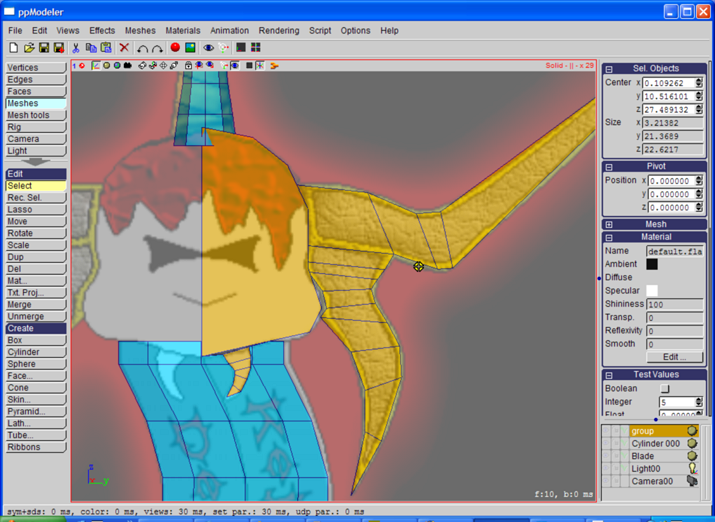
Now, we will move the curves to approximate the shape of these antennas:
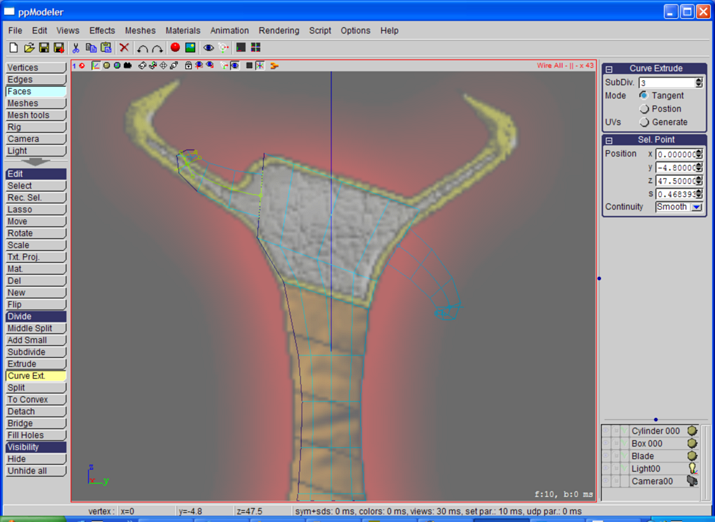
Select a curve by clicking on one of its points.
When a point is selected, the tangent is displayed (and can be moved) and
a circle to change the size of the extrusion:

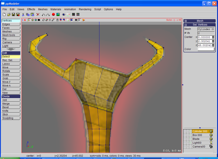
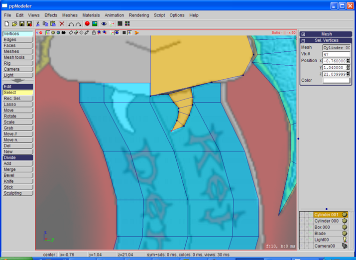
Now, back in the 'Vertices' toolbox, finish the antennas by moving the vertices:
Finishing the Cross
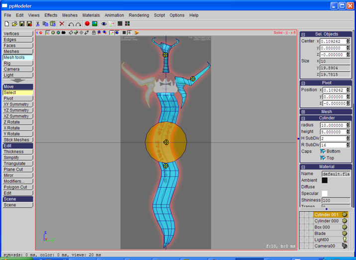
In the 'Meshes' toolbox, create a cylinder, with 16 'R SubDiv' and 2 'H subDiv'.
Then rotate it by 90 degrees around the y-axis:
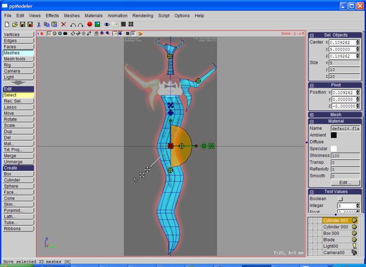
In the 'Mesh tools' toolbox, activate the 'Plane Cut' tool. There, select the 'XZ Plane':
In the 'Faces' toolbox, select the face created in the cut plane:
Delete it, and back in the 'Meshes' toolbox, move the half cylinder in place:
In the 'Vertices' toolbox, move the vertices to match the shape of the cross:
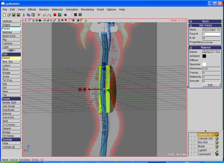
In the 'Faces' toolbox, select the face shown bellow:

Activate the 'Add Small' tool:
Activate the 'Extrude' tool, and extrude the face 4 times (with the 'Enter' key):
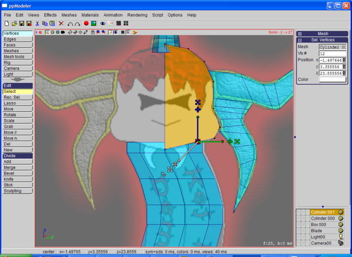
Activate the 'Middle Split' tool to add a vertex in the middle of the last face:
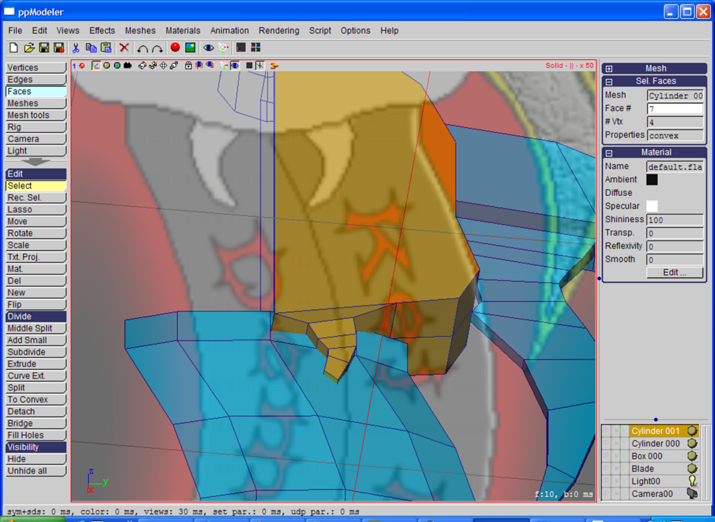
In the 'Vertices' toolbox, move the vertices of the extruded part:
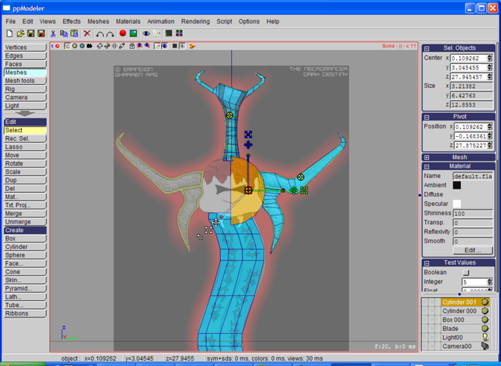
In the 'Meshes' toolbox, select the 2 meshes that compose the Cross:
Activate the 'Merge' tool, and enter 'Cross' when the name of the group mesh is asked:
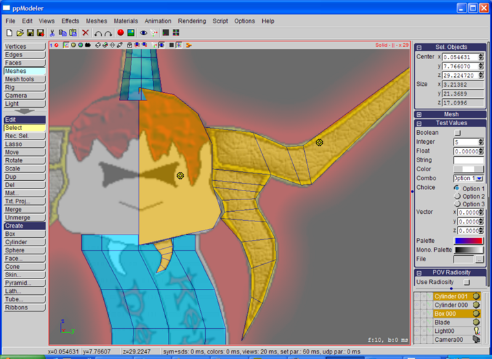
In the 'Mesh tools' toolbox, activate the 'Mirror' tool and
select the 3 red vertices shown bellow. These 3 vertices define the mirror plane:
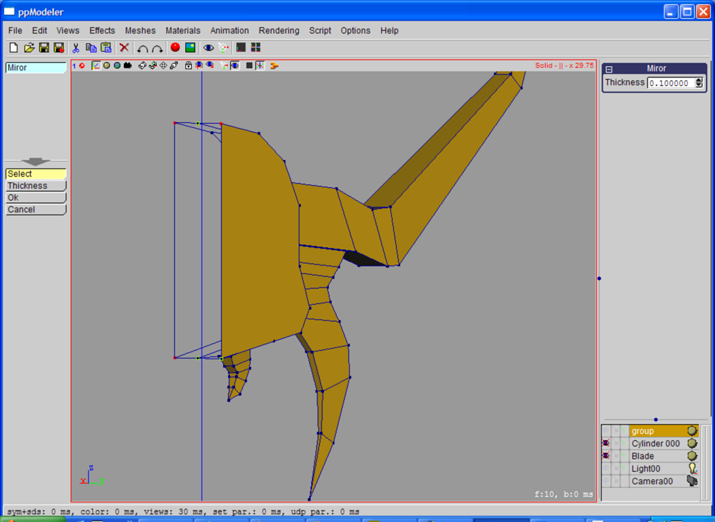
Press the 'Ok' tool. A popup is open asking if you want to create a symmetrical object:

Answer Yes. Here is our sword. Materials and textures are missing,
but this will be done in another tutorial.
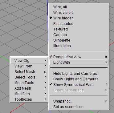
Before saving a last time, go to the 'Phong' drawing mode ('d' key as many time as needed).
Move the point of view until you find a nice one.
Right click, and in the popup menu, select 'View Cfg.->Set as Scene icon'.
The current view will be used as preview when browsing the file in ppModeler:
Here is our finished sword model: